BIT-101
Bill Gates touched my MacBook Pro
Isometric drawing is always a fun thing to work on. I say always because I’ve created many isometric frameworks over the past 20+ years. I think I wrote a book chapter or two about it, and published a couple of Coding Math Videos about it … 10 years ago (OMG):
In those videos I discussed the difference between true isometric, where everything is “one angle” and dimetric, where the width and height of a tile are generaly in a 2:1 ratio. I drew some tiles manually, and loaded in prerendered tile sets and drew those all in various locations. I used the dimetric version, as for that kind of pixel art, it works out better (as described in the videos).
All that’s good but in recent years I’ve been taking a very different approach to doing isometric. Rather than just drawing flat faces, or pre-rendered isometric tiles that someone has hand-drawn - usually at a fixed size - I wanted to draw isometric shapes of varying sizes, with dynamic, high resolution textures, with (somewhat) dynamic shading. I’ve made a few attempts at this, and while it generally works pretty well, I generally got hung up on the API or interface to creating an isometric box, sizing it, positioning it, assigning textures for each of its three faces. For a single box, that’s not too bad, but when you have a bunch of boxes, and you want each one to have a different color and texture… it gets crazy fast. And the last few iterations I did on this were just so frustrating to use that I never used them.
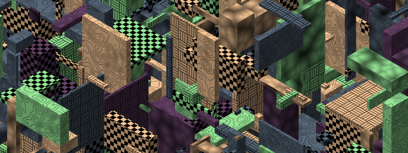
But my most recent attempt is promising and I’ve been having a ton of fun cranking out random images with it over the past few days.
And my recent color palette work has really paid off in making those images look better than they would have.
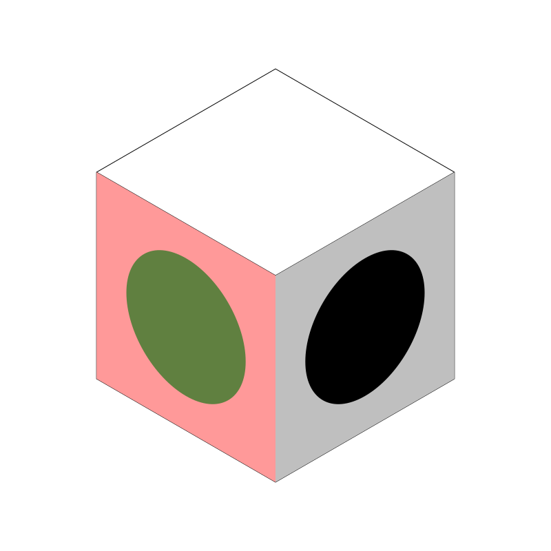
Let’s start drawing a single box in a fixed location with a fixed size and fixed coloring. I’m going to be doing true isometric rendering here, meaning that our angles and sizes for each face are going to be the same. Here’s a simple box:
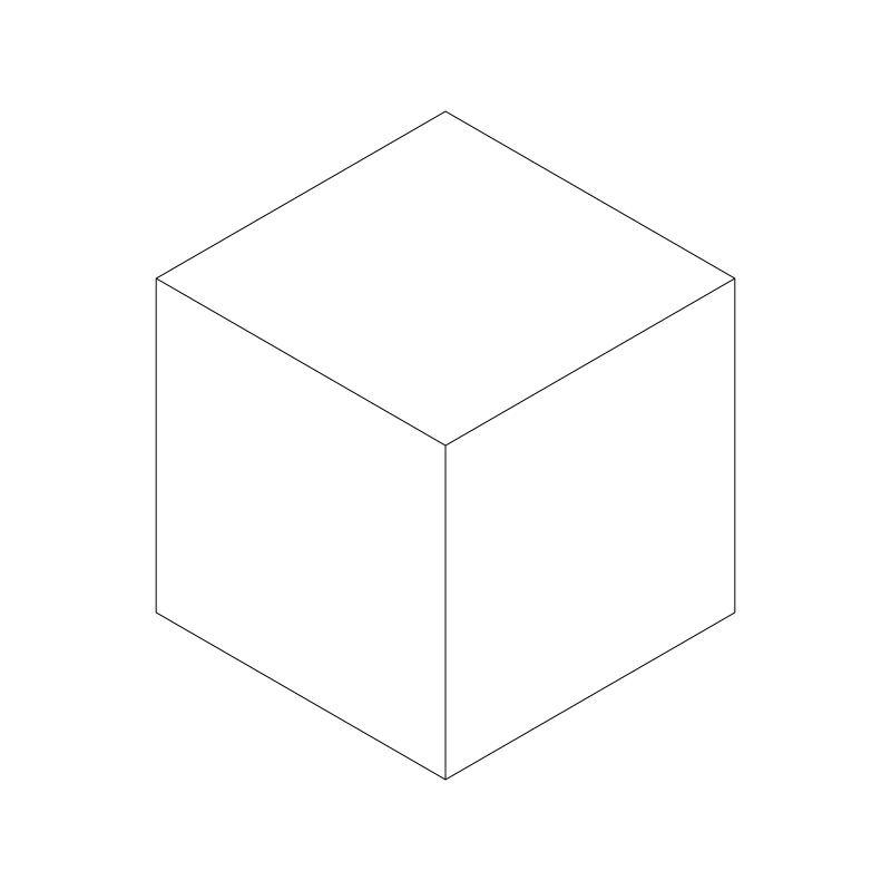
It’s composed of three identical diamond shapes. The obtuse angles are all 120 degrees and the acute angles are all 60 degrees. Every line drawn there is exactly the same length. Hence, isometric - “one measure”. Also, if you removed the internal lines, you have a perfect regular hexagon. The world needs more hexagons.
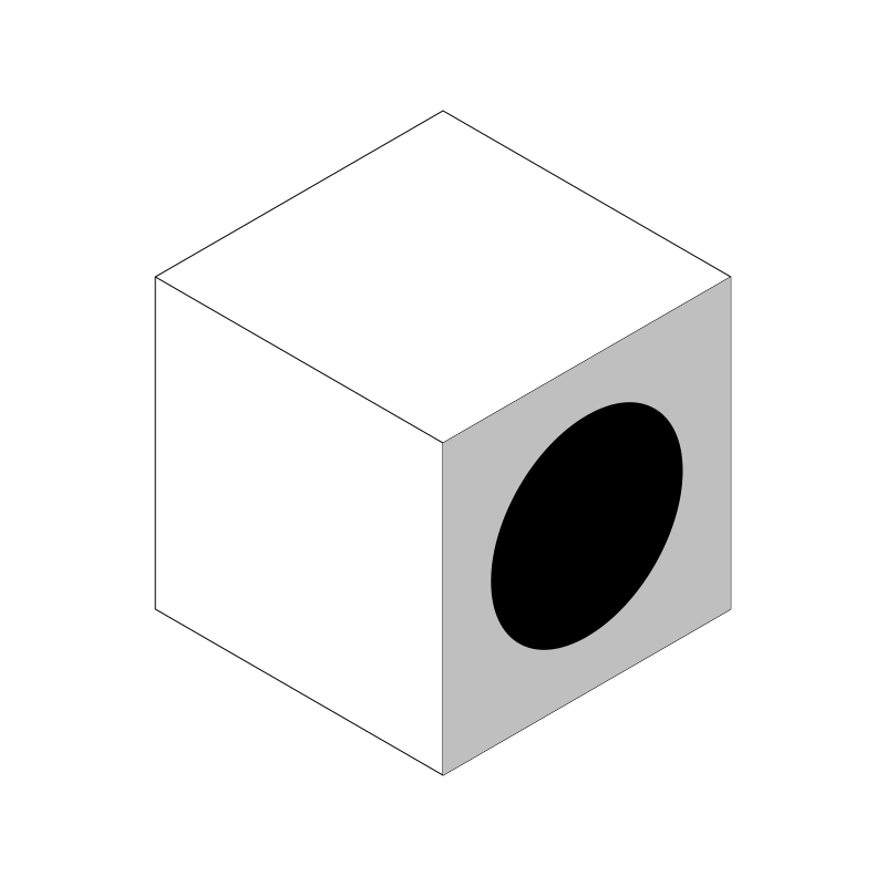
Now, I want to draw a “texture” on each one of these faces. Don’t get caught up in the word “texture”. I just want to draw something there, a flat color, a pattern, random noise, whatever. But I want whatever I draw there to look like it was actually sitting on that face of the box. For example, I don’t want to draw a circle like this:
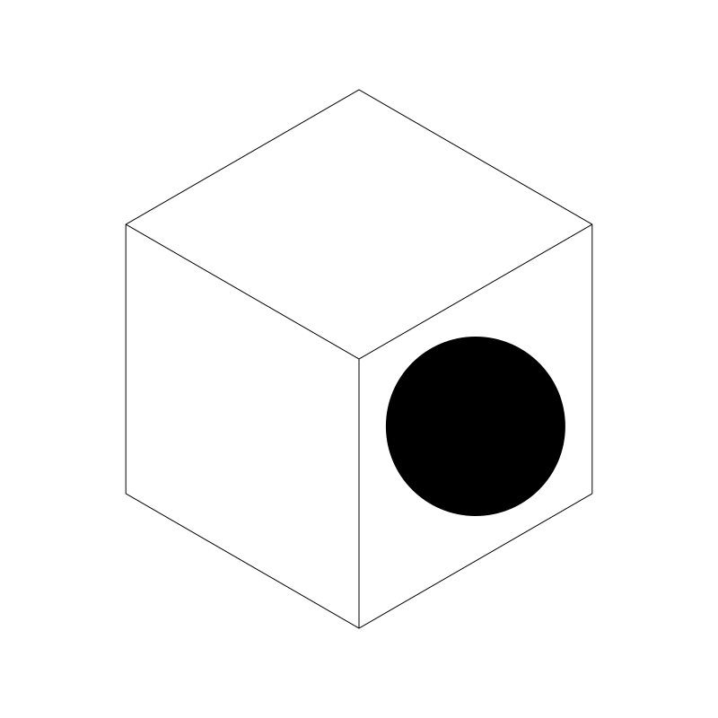
Yuck! No! I want it to look like there’s a circle on that face of the box and it’s rotated and skewed like the face itself. Consider that the face of that box is represented as a square - the way you would see it if you were to walk round to the right and crouch down so you were looking at it head on.
So, how do we distort that square, and whatever is in it, to look like the isometric box face we see?
The answer: with 2D affine transforms. Enter the Matrix!
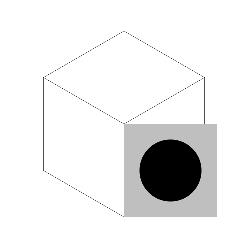
First, I’ll just draw the untransformed face. A 300x300 pixel square filled with gray and a black, 100-pixel radius circle inside of it. Its origin point is the center of the box. I know it’s 300x300 because I made the isometric box with sides of 300 pixels.
Now I need to kind of skew the box up and a bit to the left to make it fit in that face. Through a bit of analytical reasoning, working out the math, and a WHOLE LOT of trial and error, I came up with a transformation matrix that I can apply to the canvas before drawing that puts that face right into place. Here it is:
[sin(pi/3) -0.5]
[    0       1 ]
[    0       0 ]
Most drawing APIs have a way to set the transformation matrix of a canvas or context object. In JavaScript for example, you’d do it like this:
context.transform(Math.sin(Math.PI/3), -0.5, 0, 1, 0, 0);
I think in Processing, it looks like:
applyMatrix(sin(PI/3), -0.5, 0, 1, 0, 0)
I’m using a Go wrapper for CairoGraphics with a whole ton of custom functions and currently it looks like this:
context.TransformValues(math.Sin(pi/3), -0.5, 0, 1, 0, 0)
For the rest of this series I’ll pretent I’m using JavaScript.
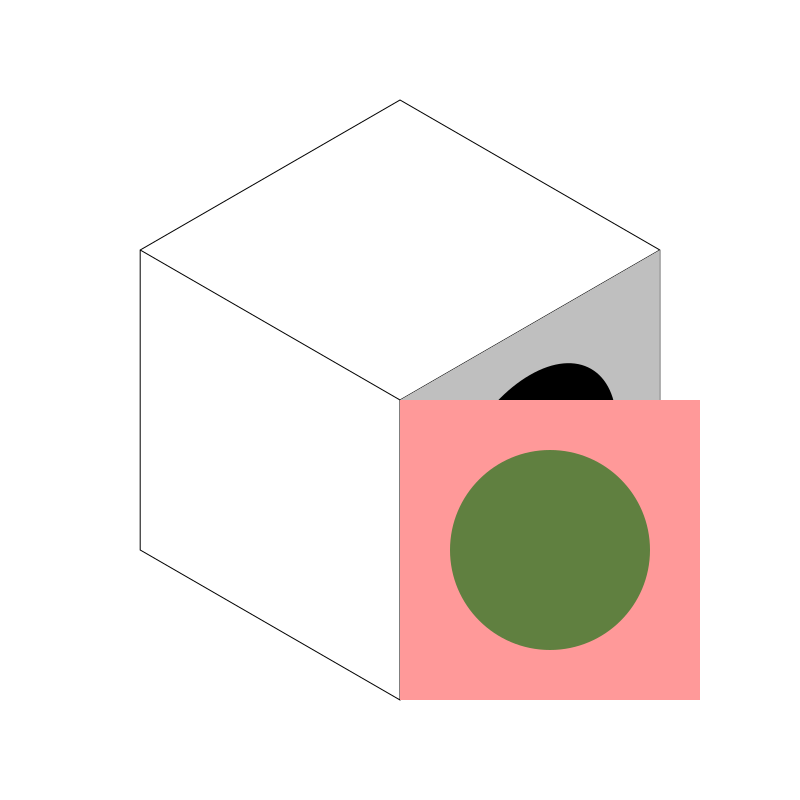
Anyway, if you apply that matrix just before drawing the square/circle shape in the last image, you get:
Voila! Perfect! To be fair, this was the simplest one, but let’s do the rest!
Hot tip: make sure you save the state of your context before you do each set of transforms, and restore it before doing the next set. Otherwise, you’ll have multiple transforms layerd on top of each other and you’ll get very confused.
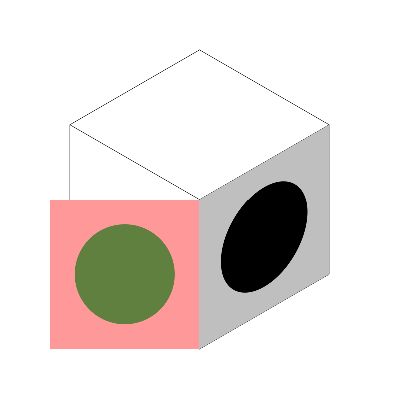
Starting with the left face, I’ll draw another slightly different “texture” and then transform it. First, the untransformed square:
Now, I could flip that box around that center line and then skew it upwards, but say my texture had some text in it, or something else I did not want to appear backwards. So what I’ll do is first slide it up to the left by 300 pixels using a translate, something like:
context.translate(-300, 0);
Now we are here:
Now we just need to skew it up. Here would be the code for that:
context.transform(Math.sin(Math.PI/3), 0.5, 0, 1, 0, 0));
That’s essentially the same transform we used for the right side, but with a positive 0.5 instead of a negative one this time. This causes it to skew from the opposite side.
Now if we add that transform after the translate, we get:
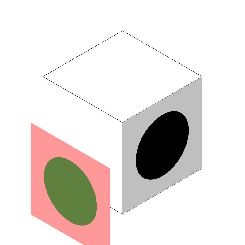
That’s obviously wrong. It has to do with the order of matrix operations. This is something that it takes wrapping your head around. Often you have to apply them in what seems to the brain to be the inverse order of what you want to do. If we do the transform and then the translate, like so…
context.transform(Math.sin(Math.PI/3), 0.5, 0, 1, 0, 0);
context.translate(-300, 0);
Then we are golden!
Side note, there are ways to combine multiple transforms into a single matrix, but I’m fine with making two or three calls. In any case, you’d have to make two or three calls to assemble the final matrix anyway, so I’m leaving it as is.
Other side note: earlier I had referenced the setTransform method, but in this case you want to use the transform method. The difference here is that transform will alter the existing transform, adding a new transform to it, whereas setTransform will remove any previous transform that had been applied and then transform the context as specified. Make sure you know the difference between these two and use the right one.
Onto the final side, the top! I’ll make another face, untransformed at first.
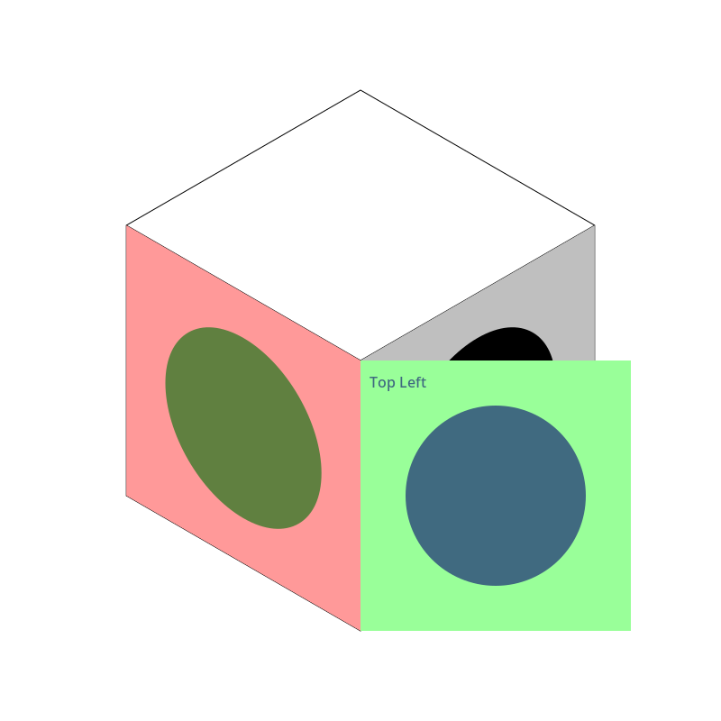
Here, I labeled one corner, “top left” to make a point. With the right face, it was a simple skew upwards. With the left face it’s pretty obvious that we wanted to slide the face over and skew it up, to keep the same orientation we had. But on the top, you have a choice. How should that top face be aligned? With the top left corner on the left side, or at the top? I think putting it on the right or the bottom would make it look upside down, but the first two choices seem equally arguable. I’m going to put it at the left side.
I won’t go through it step by step, but here are the transforms I worked out:
context.rotate(-Math.PI / 3);
context.transform(Math.sin(Math.PI/3), 0.5, 0, 1, 0, 0);
context.translate(0, -300);
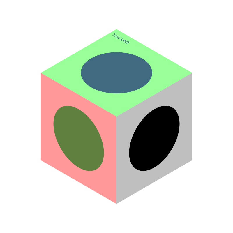
There are probably other ways to do it, but these, in this order, give us this:

At this point, I’ve removed the original line drawing, so all you’re seeing is the three faces.
If you want the top left to be up in the top, you can use this set of transforms:
context.rotate(Math.PI / 3);
context.transform(math.Sin(Math.PI/3), -0.5, 0, 1, 0, 0);
context.translate(-300, -300);
Now, for every box, for every face, I can just draw to it like I was drawing to a regular 300x300 pixel canvas. Here, I just drew three different textures, that I already had sitting around in my library:
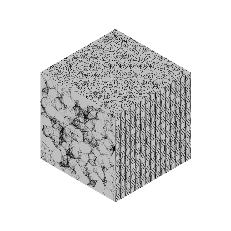
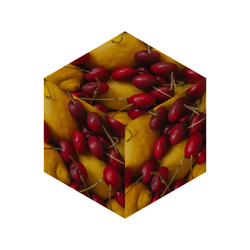
I can even load in images to apply to each side…
OK, that’s pretty good for a first post. In future posts, I’ll cover lighting/shading, sizing, positioning and a few other things.