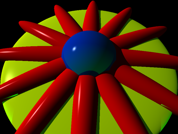
Anyone who follows me on twitter has seen what I’ve been up to in the last month and a half or so. But to hop on a meme from last year…
How it started: {.wp-block-heading}
September 18, 2022
How it’s going: {.wp-block-heading}
October 23, 2022
Not bad for 35 days of nights and weekends, if I do say so myself, but let’s go back to the start and take an image-filled journey.
It started in a book store
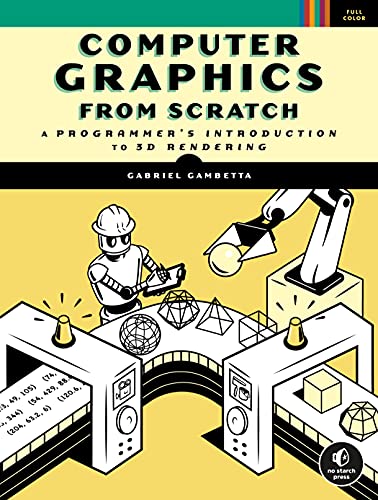
My wife, daughter and I are all book addicts. Our idea of someplace fun to go on the weekend is Barnes and Noble, which is about a ten minute drive down the highway. We were there one Saturday and I saw this book and started looking through it:
The first half of the book is about ray tracing and the second half is about rasterized 3D. The content looked really accessible and even just skimming through it, it seemed like something I could follow along with and code. I recently got an oreilly.com subscription, so I was able to access the book there, and had the first image you see above rendered in no time. And I understood what was going on with the code. I was hooked!
What is Raytracing?
I’m absolutely not going to try to teach you raytracing, but I’ll try to give you a 10,000 foot view.
The two major schools in 3D rendering are ray tracing and rasterization. Rasterization usually involved creating a bunch of triangles or other polygons out of a bunch of 3D points, figuring out how to fill in those triangles and filling them in. I’ve coded that kind of thing from scratch multiple times at different levels of thoroughness over the last 20 years.
Raytracing though, is something I’ve never touched. It involves making a model of 3D primitives and materials and lights, and then shooting out a ray through every pixel in the image, seeing what that ray hits, if anything, and coloring it accordingly.
A good analogy from the book is if you held a screen out in front of you and looked through each hole in the screen from a fixed viewpoint. Left to right, top to bottom. When you looked through that one hole, what did you see? Color a corresponding point on a canvas with that color paint. You might see nothing but sky in the top row of the screen, so you’d be doing a lot of blue points on the canvas. Eventually you’d hit some clouds or trees and do some white or green dots. Down lower you might hit other objects – buildings, a road, grass, etc. When you worked through all the holes in the screen, you’d have a completed painting. If you understood that, you understand the first level of raytracing.
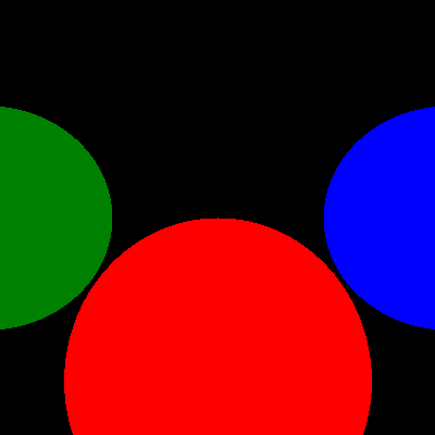
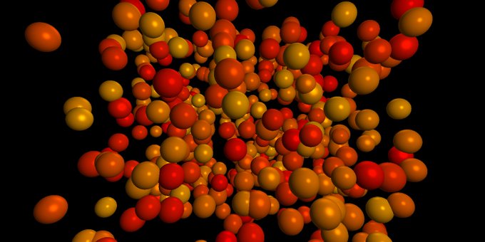
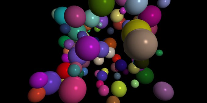
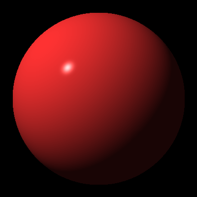
So you model three spheres and say they are red, green and blue. You shoot a ray from a fixed “camera” point, through each pixel position in your image. Does it hit one of the spheres? If so, color that pixel with the color of the sphere it hit. If not, color it black. That’s exactly what you have here:
A ray is a mathematical construct consisting of a 3D point (x, y, z) and a direction – a 3D vector (also x, y, z). So the first step is to get or create a library of functions for manipulating 3D points and vectors and eventually matrices. There’s a fairly simple formula for finding out if a ray intersected a sphere. It will return 0, 1 or 2 points of intersection. Zero means it missed entirely, one means it just skimmed the surface, and two means it hit the sphere, entered, and exited.
Of course a single ray may hit multiple objects. So the algorithm has to find the first one it hit – the intersection closest to the origin of the ray. But… it’s entirely possible there could be objects behind the camera, so you need to filter those out.
Lighting, shadows, reflection
The first image looks a bit flat, but lighting, shadows and reflection take care of that. Add to your world model one or more lights. There are different types of lights, but point lights have a point and an intensity. The intensity can be a single number, or it could be an RGB value.
When you find your point of intersection for a given pixel, you then need to shoot another ray from that intersection point to each light. Can the ray reach the light without being blocked by another object? If so, what is the angle at which the light is hitting the object at that point. If it’s hitting straight on, that part of the object will be brighter. If it’s hitting at nearly 90 degrees, it’s just barely lighting it.
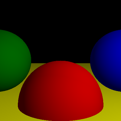
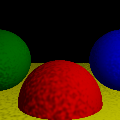
And that’s just for diffuse material. But that gives you this:
You can tell that my light in this picture is off to the right and a bit higher than the spheres. You’ll also notice that there seems to be a floor here, even though I’ve only mentioned spheres. The trick to that is that the yellow floor i just a very large sphere. But it also illustrates that closest intersection point. For some pixels the ray hits the yellow floor sphere first, so you don’t see the red sphere, but in other areas, it hits the red sphere first, so it blocks out the yellow one.
In order to figure out that light/angle part, you need to know the “normal” of the surface. That’s another ray that shoots out perpendicular to the surface at that point. I knew from previous dabbles in 3D graphics that if you start messing with that normal, it changes how light reacts with the surface. So I took a bit of a diversion and used a Simplex noise algorithm to alter the normal at each point of intersection. I just hacked this together on my own, but I was pretty much on the right track.
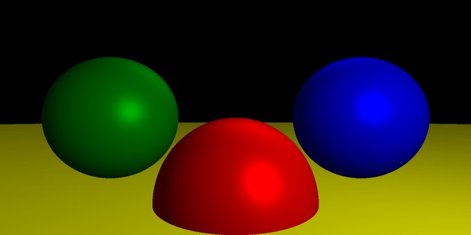
But getting back on track, some materials are more shiny and the light that reflects off of them depends on the angle you are looking at them from. So there’s another calculation that takes into account the surface normal, the angle to the light, and the angle to the camera or eye. This gives you specular lighting.
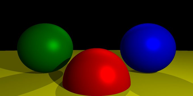
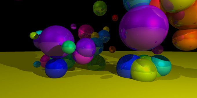
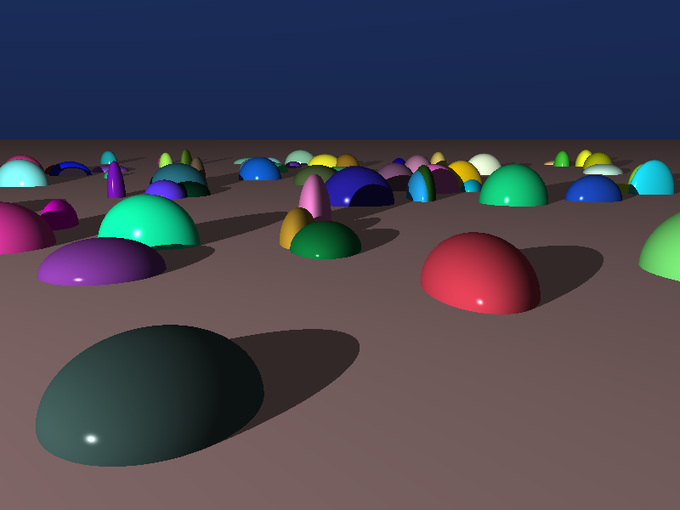
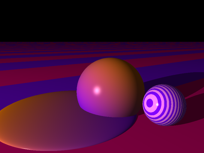
Getting better. But then there are shadows. When you are shooting that ray out from the intersection point to each light, you have to see if it intersects any other object. If so, that light does not affect the color of that pixel.
Here, there are multiple lights, so you see shadows going off in different directions. Already things are starting to look pretty cool.
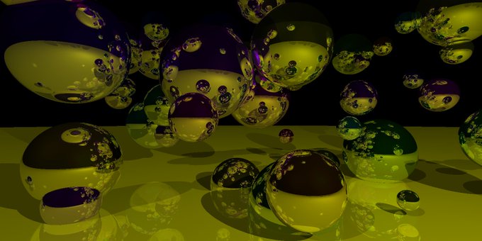
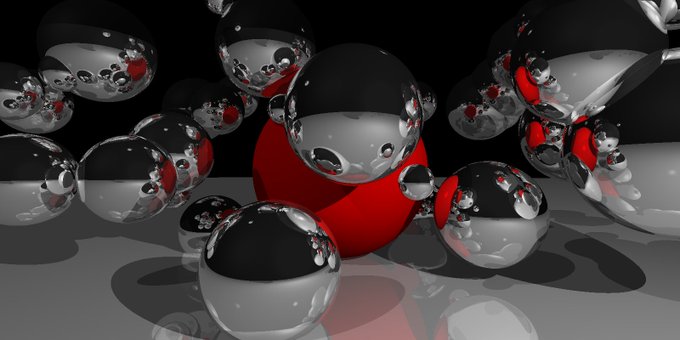
Finally, reflections. When a ray hits an object, and that object is reflective, it’s going to bounce off and hit some other object, which is going to affect the final colorization of that pixel. It can be confusing because this is all being calculated in reverse of the way light works in the real world. We’re going from the destination and working back to the source.
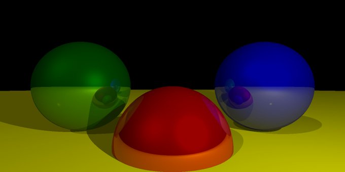
If you have multiple reflective objects, the light might wind up reflecting back and forth between them for quite a while. This is not only very costly, but it has quickly diminishing returns, so you usually set a limit on how many levels of reflection you want. So now you are figuring out the color of a given pixel by factoring in the surface color, each light and its angle, what kind of material you have, and all possible reflections. Sounds intimidating, but when you figure out each piece one by one, they all fit together way too logically and just work to create something like this:
And that is about as far as I got with the first book. Spheres, lights, shadows, materials, reflections. I could change the size of the spheres and move them around, but couldn’t deform them in any way. Still, with all that, I was able to have a jolly good bit of fun.
Phase 2 – The Next Book
Getting this far took me just about a week. Could have been faster, but every time I coded a new feature I’d spend an hour or several playing with it. I was excited but I needed more than simple spheres. I wanted to mess with those spheres, squish them and stretch them and apply images and patterns and textures to them. I wanted a real floor and cubes and cylinders and cones and whatever else I could get.
The Computer Graphics from Scratch book was great and I highly recommend it if you want a quick jump into the subject. One thing I particularly loved about it is that it wasn’t the kind of book that just dumps a lot of code on you and explains it. It gives you the concepts, the formulas and maybe some pseudocode and it’s up to you to choose a language and figure out the implementation details. I wound up doing mine in Go because its the language I am currently most comfortable with. But I think the author does have some sample code somewhere that is done in JavaScript.
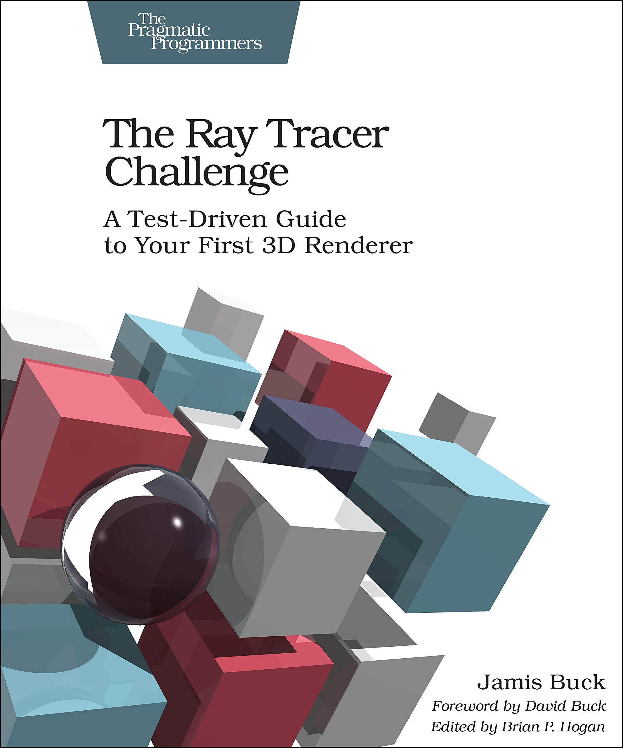
But I was ready for the next part of the journey. So I found my next book:
Oh yes, this is the one! This one goes deep and long and it took me almost four weeks to get through, but I could not put it down. Again, I’d learn something new in the first hour or so of an evening, and spend the rest of the evening messing around with it and rendering all kinds of new things using that concept.
This is honestly probably one of the best written technical books I have ever read. Like the first one, it gives you no source code and is not tied to any language. Again the author provides concepts, algorithms and some pseudocode where needed. But as the cover says, it’s a test driven approach. I cringed at first, but I was so happy for this approach as I got deep into it. For each new concept the author describes what you need to do and then gives you a test spec. Like, “given this set of object with this set of inputs, calling this method should give you these values…” Very often it is as specific as, “the color value should be red: 0.73849, green: 0.29343, blue: 0.53383”. I just made those numbers up, but yeah, it’s like down to 5 digits. I was skeptical when I first saw this. Like no way can you let me choose the language and platform and implementation details and expect that I’m going to be accurate down to 5 digits across three color channels. But goddamn! It was in almost every case. I only saw some slight diversion when I got down into transparency and refraction. And then I was still good down to 4 digits. Any time I was off by more than that, I eventually found a bug in my own code, which, when fixed, brought it back to the expected values. Amazing! These tests caught SOOOOOO many minor bugs that I would have been blissfully ignorant of otherwise. It really sold me on the value of testing graphical code, something I never really considered was possible. Brilliant approach to teaching!
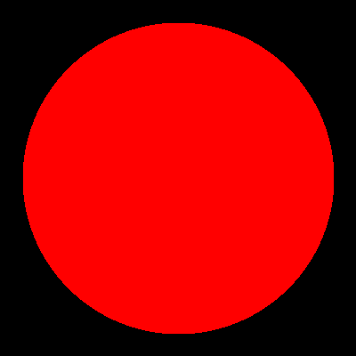
The first few chapters were slow. It was building up that whole library of points and vectors rays and matrices and transformation functions. And then finally the camera and world and spheres and intersections. It wasn’t until Chapter 5 that I could render my first sphere! And I was back to this:
But we move pretty quickly from there to lighting things up:
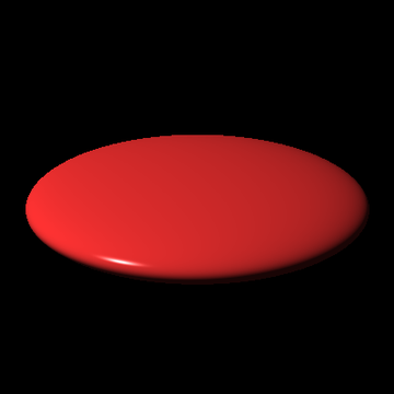
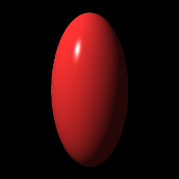
And then right away into transforming those spheres!
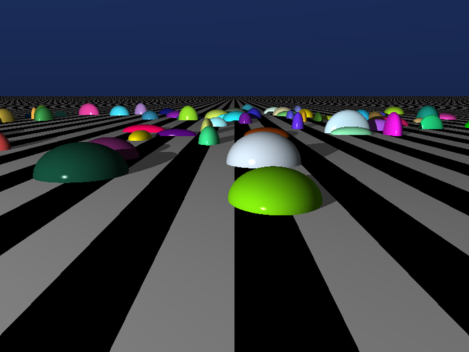
And then into shadows and finally beyond spheres into a real plane object!
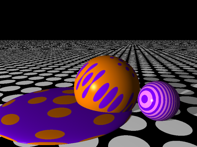
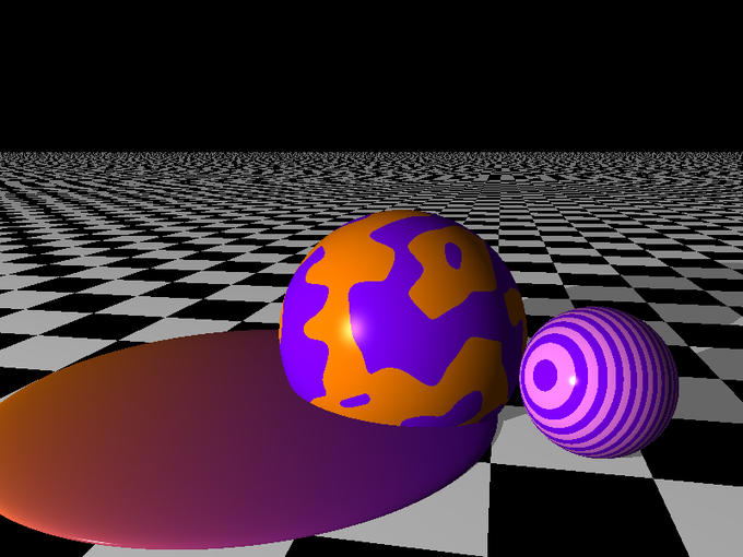
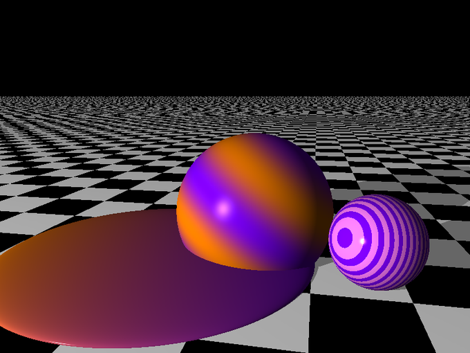
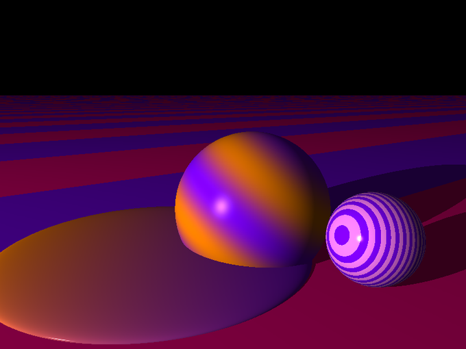
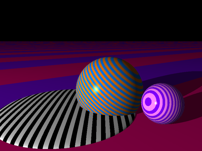
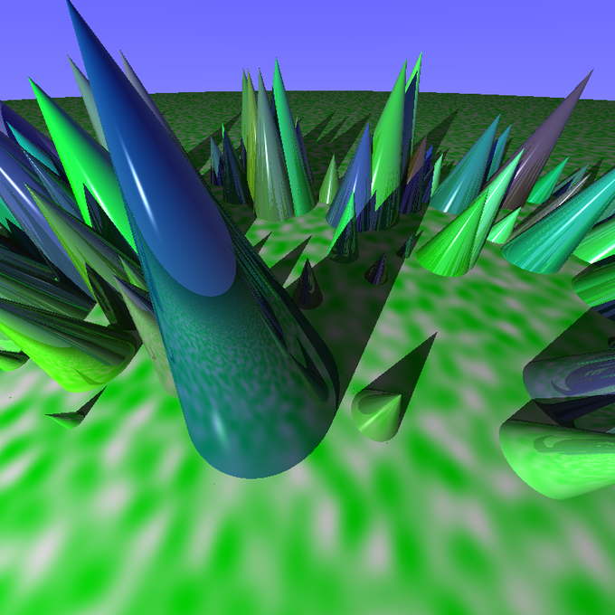
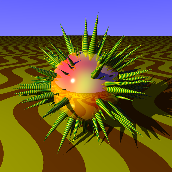
Then we got to an exciting part for me: patterns. Algorithmic ways of varying a surfaces. The author explained a few – stripes. checkers and a gradient, but I went off on a wild pattern tangent of my own.
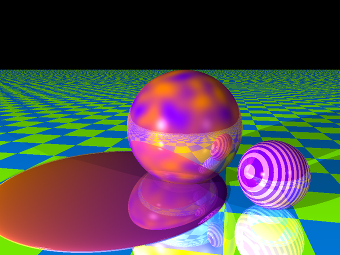
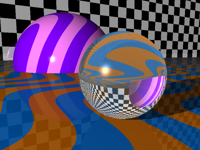
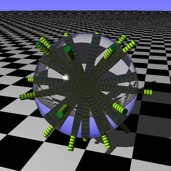
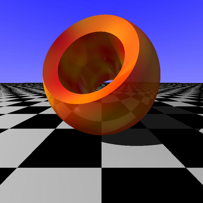
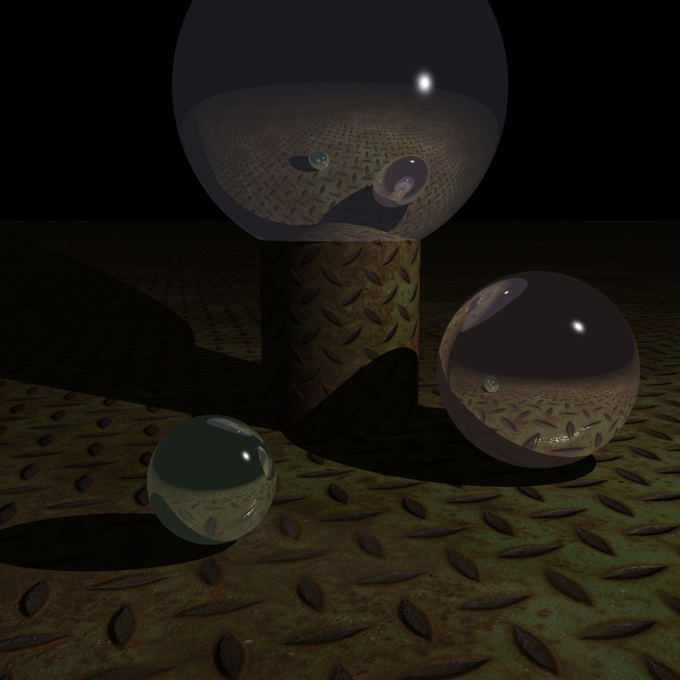
Eventually I got back on track and got back through reflection and then on to transparency with refraction!
The refraction part was the hardest so far. The code itself got pretty involved but beyond that it’s really hard to compose a compelling scene with transparent, refractive objects. It’s way too easy to overdo it and it winds up looking unrealistic. Best used with a light touch.
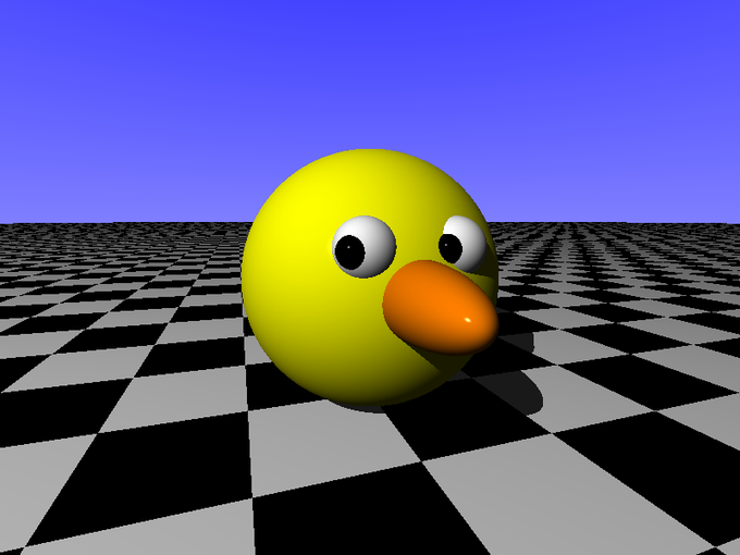
I took another short diversion into trying to model some simple characters. This one cracked me up.
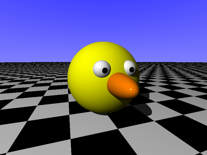
It wasn’t intended, but it wound up being a dead ringer for this classic:
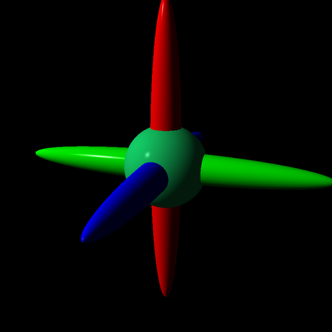
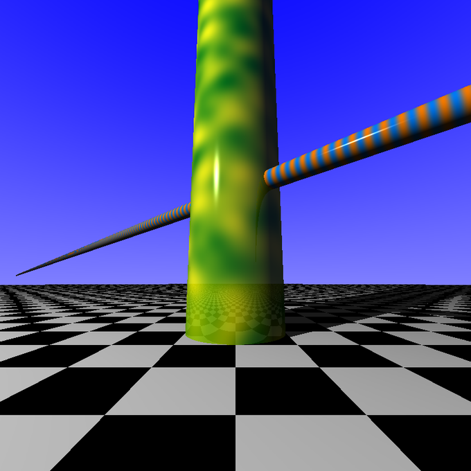
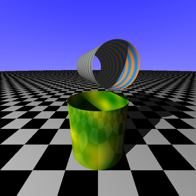
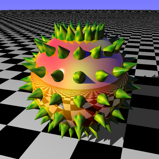
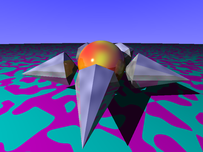
Finally we got onto new object types. Cubes, cylinders, cones:
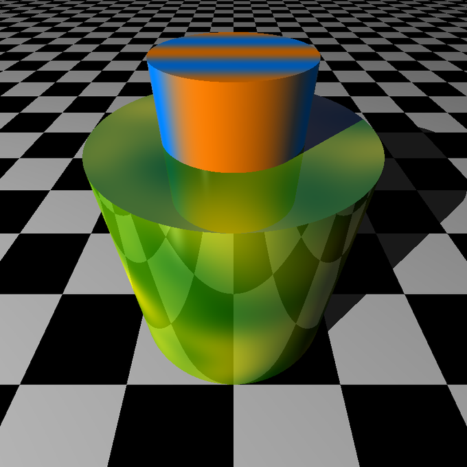
And I took some diversions into combining these in interesting ways.
Then we created triangles. And built shapes up from them.
There was a good chunk of that chapter devoted to loading, parsing and rendering object files and smoothing triangles out, etc. This was the one of the few parts of the book I jumped over because I’m not really interested in loading in pre-built models. The other part I jumped over was bounding boxes. This is mostly an optimization technique to limit the number of objects you have to test for collisions. I’ll have to get back to that eventually.
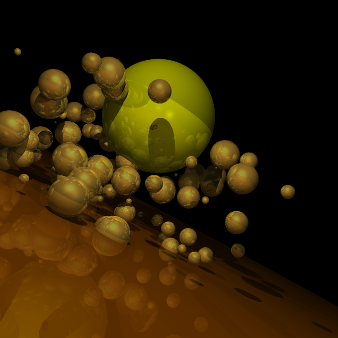
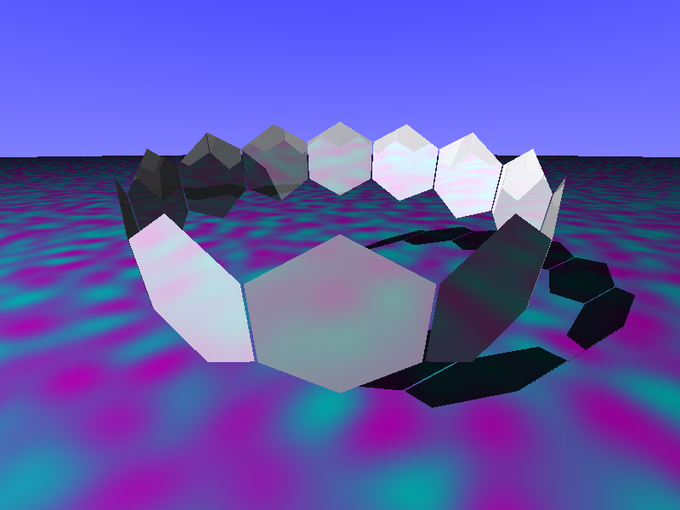
But the next exciting topic was groups and CSG groups – constructive solid geometry. This is where you take two shapes and combine them. The combination can be a union – you get the outline of both shapes, an intersection – you just get the parts of both shapes that overlap, or a difference – the second shape takes a bit out of the first. Although you can only combine two shapes at a time, a CSG group is a shape itself, which can be combined with other shapes, winding up with a binary tree kind of structure that can create some very complex forms.
This is a sphere with another sphere taking a bite out of it, and then punched through with a cylinder. I didn’t spend nearly enough time with this, but will surely do so.
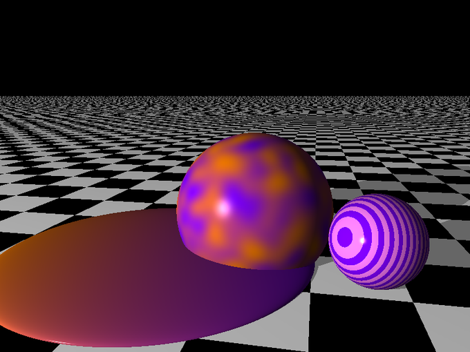
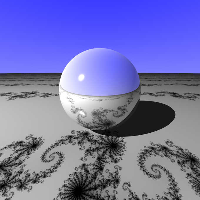
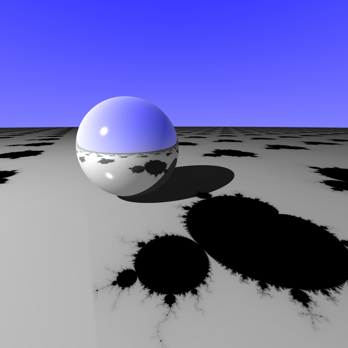
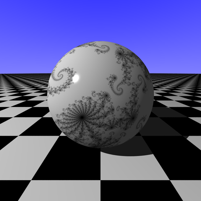
That wrapped up the book, but I continued to explore. I was still intrigued with patterns. A pattern is essentially a function that takes an x, y, z point and returns a color. Hmm… what could we do with that? I know! Fractals!
These are not fractal images mapped onto surfaces. The Mandelbrots and Julias are computed at render time. Very fun.
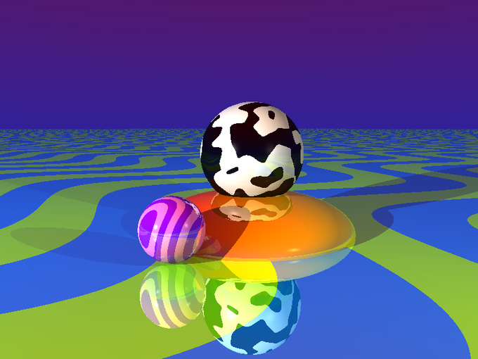
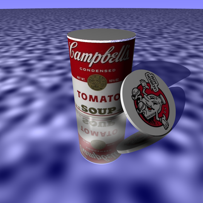
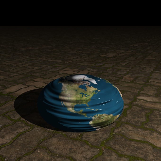
From there, I started working out image mapping on my own.
I did pretty damn well working image mapping out by myself. *Pats self on back* But it wasn’t perfect. There were some concepts I was missing and things got funky now and then. These images are the ones that worked out well. You won’t see all the ones that were just a mess.
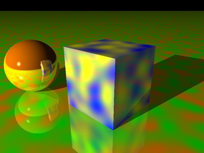
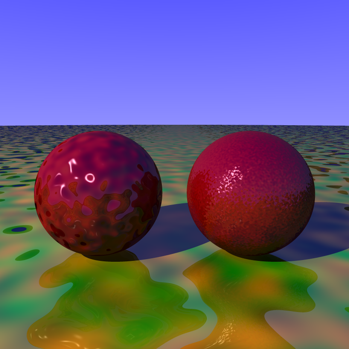
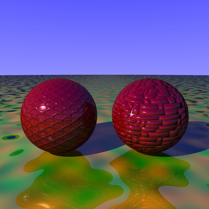
I also started exploring normal perturbation more, with noise and images – normal maps and bump maps.
Again, these look good, but I was missing some concepts.
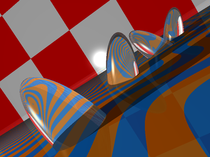
As I did more research, I eventually discovered that the author of The Ray Tracer Challenge had published a few bonus chapters on his site.
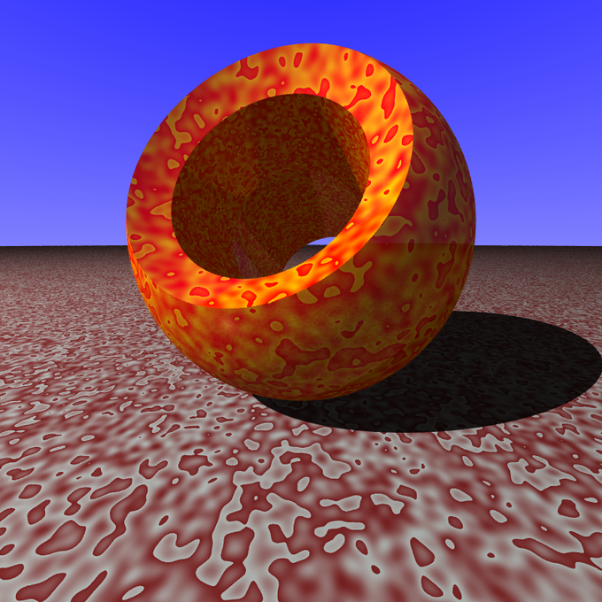
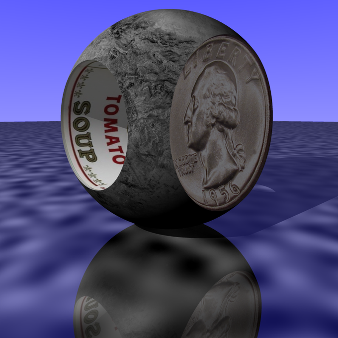
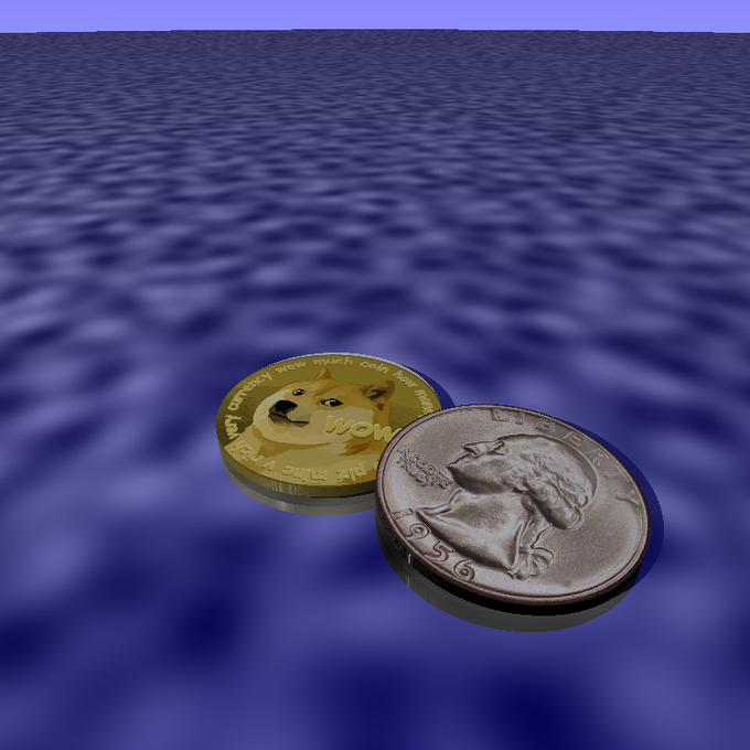
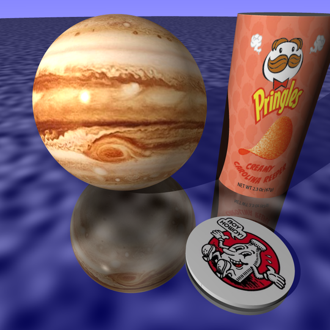
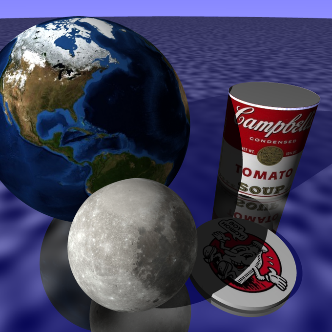
One of these was about texture mapping. This gave me the final pieces that I was missing in image and bump mapping. And I was able to do stuff like this.
Part of that chapter was about cube mapping which was super complex and contained the only actual errors I found in the author’s work. I confirmed it on the books forum site with a few other people who ran into the same issue.
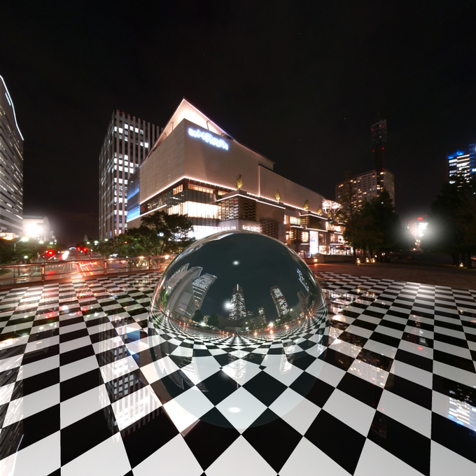
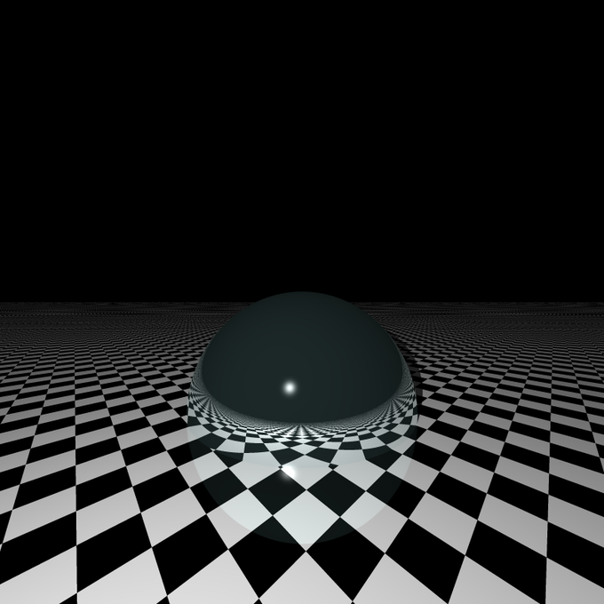
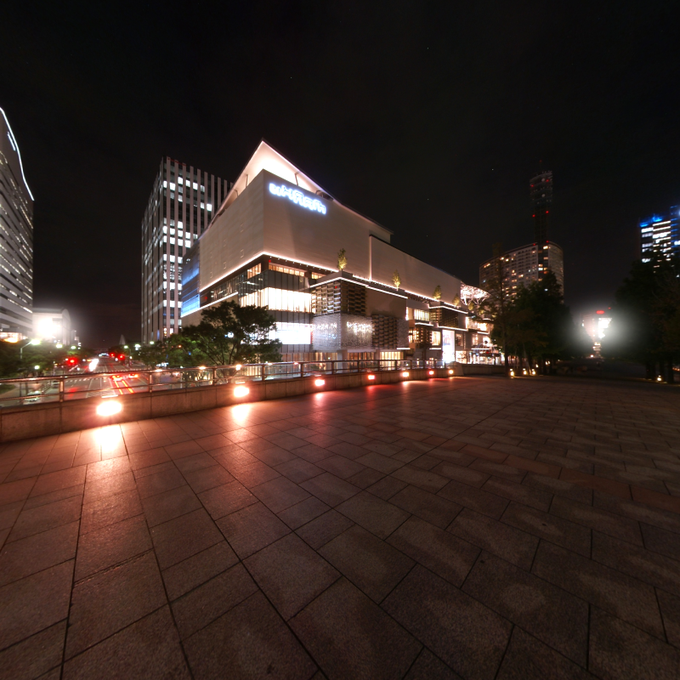
Once you have cube mapping, you can make what’s called a sky box. You make a huge cube and map images to its side. The images are specially warped so that no matter how you view them, you don’t actually see the cube. It just looks like a 3D environment. That’s the image you see at the top of this post.
Here you can see the render minus the skybox:
And here is the skybox by itself:
Though it looks like it could just be a flat background image. I could actually pan around that image and view it from any angle. Note the reflections in the full image, where you can see buildings that are behind the camera reflected in the sphere.
And there you can see some live, interactive demos of those skyboxes where you can pan around the image in real time.
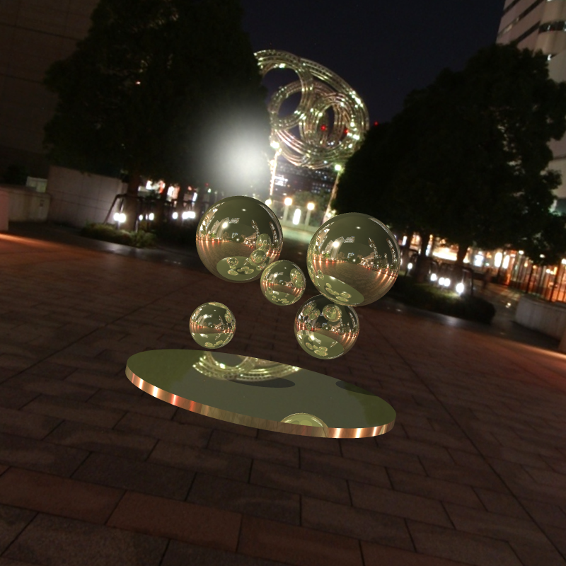
The final thing I’ve been working on recently is creating a description format for a full scene. I tried JSON and TOML, but settled on YAML as the best one to handcode a descriptor scene. Now I have an executable file that I just point to a YAML file and it creates the scene, renders it and outputs the image.
Here’s another image using that same skybox with some other objects:
This was rendered completely with this new executable. I only wrote this YAML to describe it:
One other thing I worked on was antialiasing. The way this is done is instead of just getting the color of a pixel with a single ray, you take multiple samples around fractional parts of that pixel. Some references say up to 100 samples per pixel and then average them. I’ve found that’s way too many. Actually 16 looks pretty good – it makes a HUGE difference in quality. I can’t see any difference in quality if I go past 64 samples though. But it might be different for high res images.
The Future
After 5 solid weeks of working on this in my every spare moment, I needed to step back a bit and breathe. Which for me, meant creating a vim plugin. 🙂 But I’ll be back to this before long. There is still a lot to explore in this realm.