Perlinized Hexagons
In my last post, Hexagons, I talked a bit about how cool hexagons are, and gave one method of creating a hex grid. I also used this image as a header:
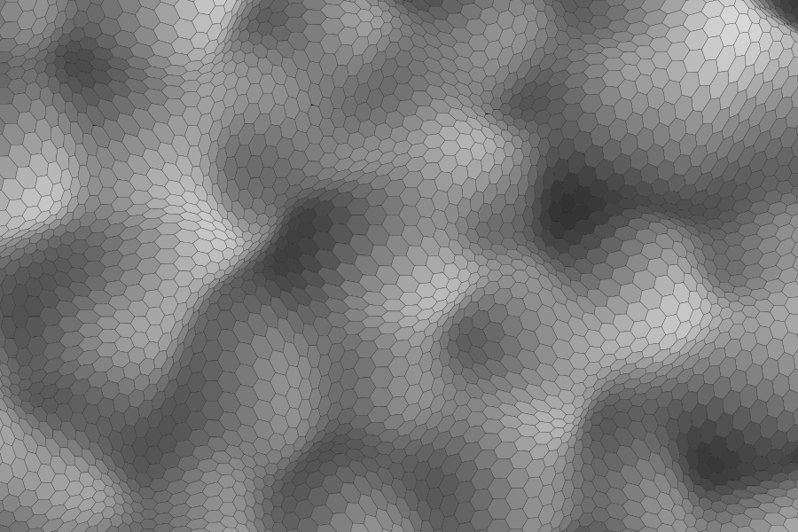
This was a bit of a tease, as I didn’t show how to create such an image. But I promised I’d come back around and give some code for it, so here we go.
First, some refactoring
As I’m sure most of you guessed, this image uses Perlin noise, but you could use any other function to get different textures. Check out my articles on flow fields (parts one and two) for more ideas along these lines. I’ll also be using the same Perlin noise library mentioned in the second of those articles.
I’m going to take the basic code from the tiled hexagons in the last article and change it up a bit. Mainly all I’m doing here is removing the translation code and calculating each x, y drawing point directly. Here’s what that looks like:
const canvas = document.getElementById("canvas");
const context = canvas.getContext("2d");
context.lineWidth = 0.5;

function hexagon(x, y, r) {
  let angle = 0;
  for(let i = 0; i < 6; i ++) {
    context.lineTo(x + Math.cos(angle) * r, y + Math.sin(angle) * r);
    angle += Math.PI / 3;
  }
  context.closePath();
}

const radius = 10;
const ydelta = Math.sin(Math.PI / 3) * radius;
let even = true;

for(let y = 0; y < 900; y += ydelta) {
  let offset = 0;
  let yy = y;
  if(even) {
    offset = radius * 1.5;
  }
  for(let x = 0; x < 900; x += radius * 3) {
    context.beginPath();
    hexagon(x + offset, y, radius);
    context.stroke();
  }
  even = !even;
}
Here’s what that gives us. Notice that I made the radius much smaller and stroked it instead of filling it.

Again, this all builds off of the last article. I had to remove the translation code because I need the exact x, y coordinates of every point of every hexagon, so I can feed that into a Perlin noise function to know how much to shift it.
Adding some noise
The Perlin function is going to make use of this library: https://github.com/josephg/noisejs. Feel free to add that to your project however you’d like. Or add a different noise function. It doesn’t really matter which one you use.
I need a function that’s going to take an x, y coordinate, calculate an offset based on Perlin noise, and return a new, shifted x, y coordinate. Since JavaScript doesn’t let us return multiple values, I’ll return and object with x, y properties. Here’s the function:
function perlinize(x, y) {
  const scale = 0.01;
  const strength = 20;
  const angle = noise.perlin2(x * scale, y * scale) * Math.PI;
  return {
    x: x + Math.cos(angle) * strength,
    y: y + Math.sin(angle) * strength,
  }
}
To revisit how a Perlin flow field works, we’re going to use 2-dimensional Perlin noise, feeding it an x, y value. Since the numbers we’re using will be in the hundreds or even thousands for pixel values, we’ll scale that down a bit with a scale value. This function returns a value from -1 to +1. Other Perlin noise functions sometimes return values from 0 to 1. Either will work just fine, but might need some tweaking. I take that value and multiply it by PI, which will give me a number from -PI to +PI. We’ll call that an angle in radians. In degrees, it would be -180 to +180. And we’ll use the sine and cosine of that angle to create an offset based with a customizable strength. Then, we return the original x, y coordinate + that x, y offset.
Now we just need to alter our code to use the perlinize function. I’ll just show the relevant function:
function hexagon(x, y, r) {
  let angle = 0;
  for(let i = 0; i < 6; i ++) {
    const p = perlinize(x + Math.cos(angle) * r, y + Math.sin(angle) * r);
    context.lineTo(p.x, p.y);
    angle += Math.PI / 3;
  }
  context.closePath();
}
And this is where this gets us.

Each hexagon still perfectly tiles because the Perlinized offset for each shared point of each hexagon should be exactly the same, at least down to an adequate degree of precision.
Shading
Now let’s add some shading. Basically we just want a grayscale value for each hexagon. To enhance the effect, the shading should be coordinated with the offset flow field values, so we’ll use the same Perlin noise settings. Here’s a function that will accomplish that:
function getShading(x, y) {
  const scale = 0.01;
  const value = (noise.perlin2(x * scale, y * scale) + 1) / 2;
  const shade = 255 - value * 255;
  return "rgb(" + shade + "," + shade + "," + shade + ")";
}
This takes an x, y coordinate and returns and rgb color string. Remember that this particular noise function returns -1 to +1. I’ll add 1 to that to have a range of 0 to 2, then divide by 2 to get 0 to 1. Then I’ll calculate a shade value by subtracting that normalized value by 255 and subtracting from 255. A bit convoluted, I know. This is all made a lot easier if you have a map range function. It would look something like this:
const n = noise.perlin2(x * scale, y * scale);
const shade = map(n, -1, 1, 255, 0);
To see how a map function would work, check out this video.
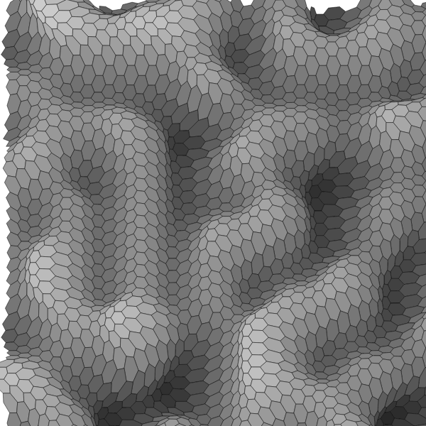
Finally, we just need to alter our drawing code to set the fill color based on the x, y of each hexagon, and do a fill before the stroke:
  for(let x = 0; x < 900; x += radius * 3) {
    context.beginPath();
    hexagon(x + offset, y, radius);
    context.fillStyle = getShading(x + offset, y);
    context.fill();
    context.stroke();
  }
And here is the result:
Summary
Don’t stop here. There are all kinds of variables and different rendering techniques to experiment with here. This is all just about taking two different concepts – hex grids and Perlin noise – and combining them in a creative way. This worked out pretty well, but there are an infinite other combinations waiting for you to discover.
Late breaking comment…
One thing I had in writing this but totally spaced out on while writing the article is that this code is extremely unoptimized. Every single x, y point here is calculated and then “perlinized” three times. OK, some of the ones on the edges only get calculated only once or twice, but you get the point.
Strategies for optimizing would probably involve creating a single point grid one time and then using a loop to draw using the pre-calculated points in that grid.
This is left as an exercise for the reader.™
Comments? Best way to shout at me is on Mastodon ![]()